Visible to Intel only — GUID: mwh1414613513009
Ixiasoft
2.3.1. Recommended Initial SDC Constraints
2.3.2. SDC File Precedence
2.3.3. Iterative Constraint Modification
2.3.4. Creating Clocks and Clock Constraints
2.3.5. Creating I/O Constraints
2.3.6. Creating Delay and Skew Constraints
2.3.7. Creating Timing Exceptions
2.3.8. Example Circuit and SDC File
2.3.7.5.1. Default Multicycle Analysis
2.3.7.5.2. End Multicycle Setup = 2 and End Multicycle Hold = 0
2.3.7.5.3. End Multicycle Setup = 2 and End Multicycle Hold = 1
2.3.7.5.4. Same Frequency Clocks with Destination Clock Offset
2.3.7.5.5. Destination Clock Frequency is a Multiple of the Source Clock Frequency
2.3.7.5.6. Destination Clock Frequency is a Multiple of the Source Clock Frequency with an Offset
2.3.7.5.7. Source Clock Frequency is a Multiple of the Destination Clock Frequency
2.3.7.5.8. Source Clock Frequency is a Multiple of the Destination Clock Frequency with an Offset
Visible to Intel only — GUID: mwh1414613513009
Ixiasoft
2.2.5.5. Correlating Constraints to the Timing Report
Understanding how timing constraints and violations appear in the timing analysis reports is critical to understanding the results. The following examples show how specific constraints impact the timing analysis reports. Most timing constraints only affect the clock launch and latch edges. Specifically, create_clock and create_generated_clock create clocks with default relationships. However, the set_multicycle_path exception modifies the default setup and hold relationship. The set_max_delay and set_min_delay constraints are low-level overrides that explicitly indicate the maximum and minimum delays for the launch and latch edges.
The following figures show the results of running Report Timing on a particular path.
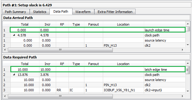
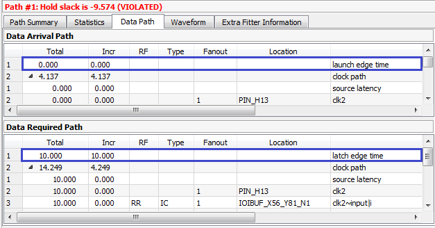
In the following example, the design includes a clock driving the source and destination registers with a period of 10 ns. This results in a setup relationship of 10 ns (launch edge = 0 ns, latch edge = 10ns) and hold relationship of 0 ns (launch edge = 0 ns, latch edge = 0 ns) from the command:
create_clock -name clocktwo -period 10.000 [get_ports {clk2}]
Figure 40. Setup Relationship 10ns, Hold Relationship 0ns
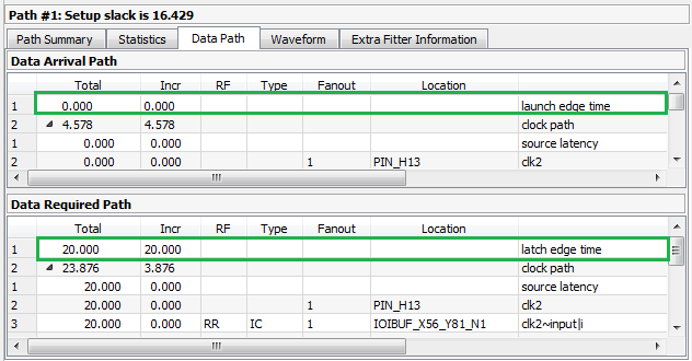
The set_multicycle_path constraint adds multicycles to relax the setup relationship, or open the window, making the setup relationship 20 ns while the hold relationship is still 0 ns:
set_multicycle_path -from clocktwo -to clocktwo -setup -end 2
set_multicycle_path -from clocktwo -to clocktwo -hold -end 1
Figure 41. Setup Relationship 20ns
The set_max_delay and set_min_delay constraints explicitly override the setup relationship. Note that the only thing changing for these different constraints are the launch edge time and latch edge times for setup and hold analysis. Every other line item comes from delays inside the FPGA and are static for a given fit. View these reports to analyze how your constraints affect the timing reports.
Figure 42. Using set_max_delay
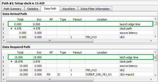
Figure 43. Using set_min_delay
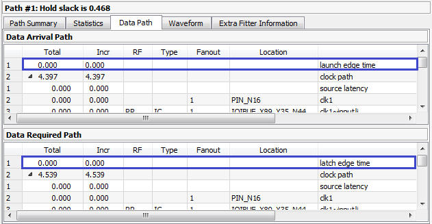
For I/O, you must add the -max and -min values. They are display as iExt or oExt in the Type column. An example is an output port with a set_output_delay -max 1.0 and set_output_delay -min -0.5:
The clock relationships determine the launch and latch edge times, multicycles, and possibly set_max_delay or set_min_delay constraints. The Timing Analyzer also adds the value of set_output_delay as an oExt value. For outputs this value is part of the Data Required Path, since this is the external part of the analysis. The setup report on the left subtracts the -max value, making the setup relationship harder to meet, since the Data Arrival Path must be shorter than the Data Required Path. The Timing Analyzer also subtracts the -min value. This subtraction is why a negative number causes more restrictive hold timing. The Data Arrival Path must be longer than the Data Required Path.
Related Information