1.4. Generating the EMIF Design Example for Simulation
For the Intel® Stratix® 10 development kit, it is sufficient to leave most of the Intel® Stratix® 10 EMIF IP settings at their default values. To generate the design example for simulation, follow these steps:
- On the Diagnostics tab, you can choose between two calibration modes: Skip Calibration and Full Calibration. (For details on these modes, refer to Simulation Versus Hardware Implementation, later in this chapter.) To reduce simulation time, select Abstract PHY for fast simulation.
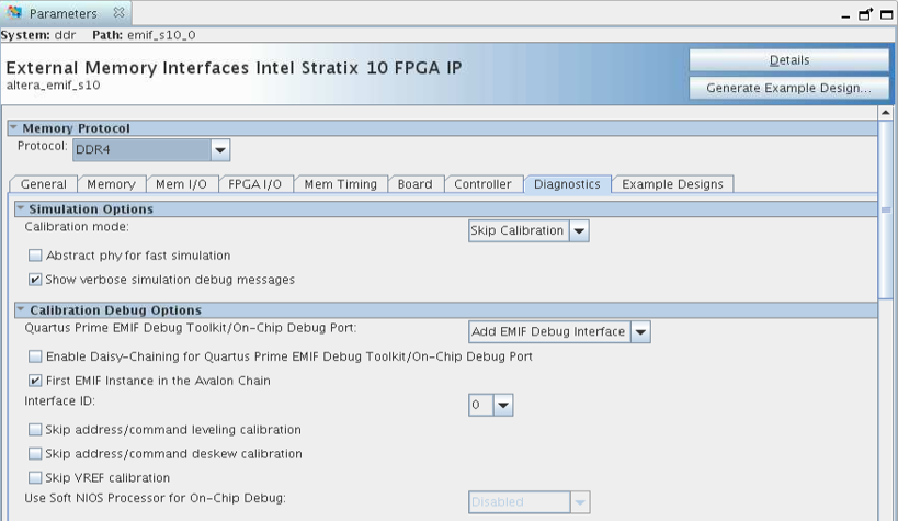
- On the Example Designs tab, ensure that the Simulation box is checked. Also choose the required Simulation HDL format, either Verilog or VHDL.
- Configure the EMIF IP and click Generate Example Design in the upper-right corner of the window.

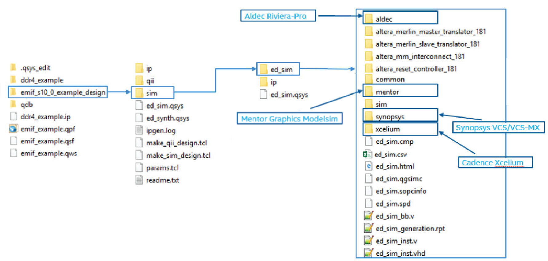
Successful generation of the EMIF design example creates multiple file sets for various supported simulators, under a sim/ed_sim directory.
Figure 4. Generated Simulation Design Example File Structure
Note:
If you don't select the Simulation or Synthesis checkbox, the destination directory will contain Platform Designer design files, which are not compilable by the Intel® Quartus® Prime software directly, but can be viewed or edited under the Platform Designer. In this situation you can run the following commands to generate synthesis and simulation file sets.
- To create a compilable project, you must run the quartus_sh -t make_qii_design.tcl script in the destination directory.
- To create a simulation project, you must run the quartus_sh -t make_sim_design.tcl script in the destination directory.