Visible to Intel only — GUID: crm1512376033626
Ixiasoft
AN 838: Interoperability between Intel® Arria® 10 NBASE-T Ethernet Solution and Aquantia Ethernet PHY Reference Design
Getting Started Intel® Arria® 10 Multi Speed Ethernet Solution and Aquantia Ethernet PHY Reference Design
Generating the 10G USXGMII Ethernet Example Design
Reference Design Walk Through
Debugging the Reference Design
Document Revision History for AN 838: Interoperability between Intel® Arria® 10 NBASE-T Ethernet Solution and Aquantia Ethernet PHY Reference Design
Visible to Intel only — GUID: crm1512376033626
Ixiasoft
Setting Up Intel® Arria® 10 GX Transceiver SI Development Kit
Follow the steps to setup the Intel® Arria® 10 GX transceiver SI development kit.
- Generate the Intel® Arria® 10 10G USXGMII Ethernet design example using Intel® Quartus® Prime Standard Edition version 17.1. Refer to the Intel FPGA Low Latency Ethernet 10G MAC Design Example User Guide for Intel® Arria® 10 Devices in the related links.
- Connect Intel® FPGA Download Cable from both development kits to your host.
- Launch the Clock Control (ClockController.exe) tool from the Intel® Arria® 10 GX Transceiver Signal Integrity Installation Package. The tool is available in arria10GX_10ax115sf45_si_v15.1\examples\board_test_system\ directory.
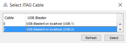
If you have two Intel® FPGA Download Cables connected to a single host, the following prompt pops up when you launch the Clock Control tool. Select a cable number to set the clocks for each development kit.Figure 3. Intel® FPGA Download Cable Selection
- Close the Intel® FPGA Download Cable selection prompt.
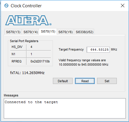
- Set Y5 to 644.53125 MHz and Y6 to 125 MHz to the Intel® Arria® 10 GX Transceiver SI development kit.
Figure 4. Clock Controller Setting
- Repeat step 3 to set the clocks for the subsequent Intel® Arria® 10 GX Transceiver SI development kit.
- In Intel® Quartus® Prime software, open altera_eth_top.qpf file.
- Click Processing > Start Compilation to compile the design example.
- Configure the FPGA using the generated configuration file, altera_eth_top.sof.
- This reference design uses the same host to control both Intel® Arria® 10 GX Transceiver SI development kits. Duplicate the system console folder from LL10G_10G_USXGMII/hwtesting directory and rename the folders to identify system console for each development kit. This reference design uses system_console_pod13_A and system_console_pod13_B folder names as an example.
- Open basic.tcl file from LL10G_10G_USXGMII/hwtesting/system_console_pod13_B/basic and set the System Console path from the system_console_pod13_B to 1 using the following command:
set port_id [lindex [get_service_paths master] 1];
- In the Intel® Quartus® Prime software, launch the System Console tool from Tools > System Debugging Tools > System Console.
- In the System Console, change the working directory to LL10G_10G_USXGMII/hwtesting/system_console_pod13_A.
- Initialize the design command list using the following command:
source main.tcl
- Initialize the Ethernet channel and enable auto-negotiation test using the following command:
SET_CHANNEL_BASE_ADDR 1 SETPHY_USXGMII_AN - Repeat step 12 to launch a new system console.
- In the System Console, change the working directory to LL10G_10G_USXGMII/hwtesting/system_console_pod13_B.
- Repeat step 14 and 15 to initialize the Ethernet channel, enable auto-negotiation, and the design command list.
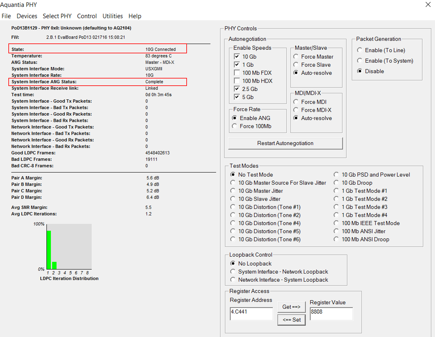
- The Aquantia evaluation board shows auto-negotiation status as completed and system is connected once auto-negotiation between Intel 1G/2.5G/5G/10G Multi-rate Ethernet PHY and Aquantia AQR105 Ethernet PHY has completed successfully.
Figure 5. Aquantia Ethernet PHY GUI