Visible to Intel only — GUID: joc1463336720637
Ixiasoft
Intel® Stratix® 10 Devices and Transceiver Channels
PCB Stackup Selection Guideline
Recommendations for High Speed Signal PCB Routing
FPGA Fan-out Region Design
CFP2/CFP4 Connector Board Layout Design Guideline
QSFP+/zSFP/QSFP28 Connector Board Layout Design Guideline
SMA 2.4-mm Layout Design Guideline
Tyco/Amphenol Interlaken Connector Design Guideline
Electrical Specifications
Document Revision History for AN 766: Intel® Stratix® 10 Devices, High Speed Signal Interface Layout Design Guideline
Option 1: Via-In-Pad Topology
Option 2: Dog-bone with GND Cutout at BGA Pad Topology
Option 3: Micro-via Topology
GND Cutout Under BGA Pads in Fan-out Configuration
Comparison of Dog-bone with GND Cutout Under the BGA and Via-in-Pad Configurations
Trace Shape Routing at the BGA Void Area (Tear Drop Configuration)
Visible to Intel only — GUID: joc1463336720637
Ixiasoft
Adding a Trace Reference to the 0201 AC Capacitor
A small plane is added as a reference plane on the anti-pad void area on both sides of the GND planes for the stripline to lower the impedance of the breakout trace. This section examines the impact of the added reference plane width.
Figure 43. Configuration of the Added Trace Reference for the 0201 AC Capacitor GND Cutout
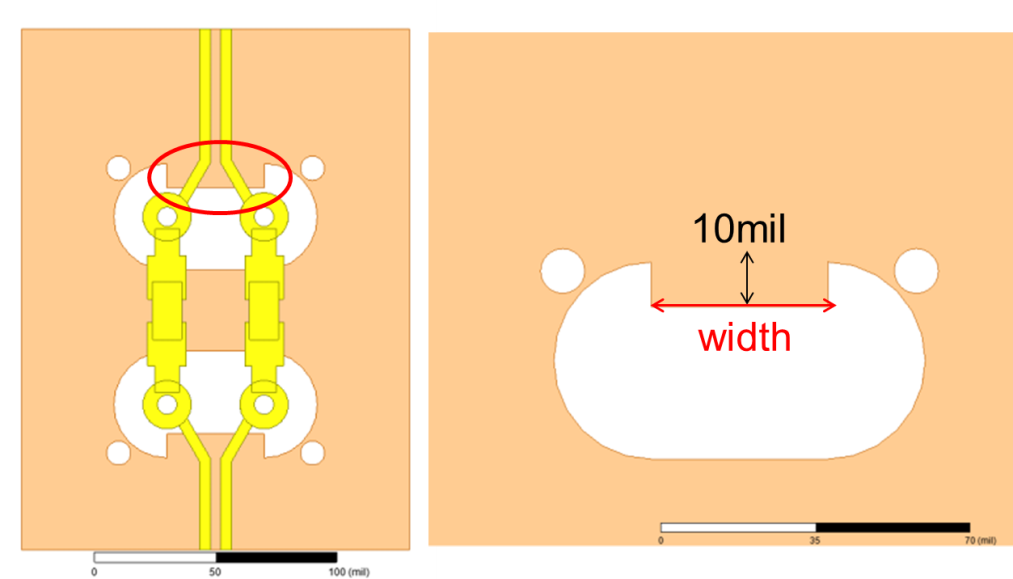
Figure 44. Differential Return Loss and TDR Performances by Different Widths of Adding Trace Reference for the 0201 AC Capacitor GND Cutout
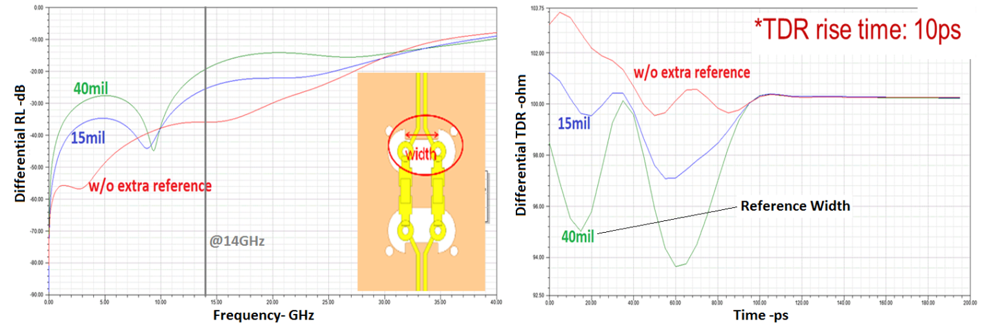
The extra reference plane for the stripline trace lowers the impedance fluctuation while connected to the signal via. A 15 mil width is a good solution for lowering impedance mismatching for this case.
If the AC capacitor is located close to the connector, it is better to use microstrip routing to reach the connector from the AC capacitor.
Figure 45. 0201 AC Capacitor Placement and GND Cutout on the PCBThis figure shows stripline routing on one end and microstrip routing on the other.
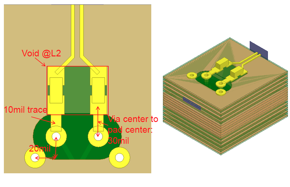
The top layer breakout performance above is preferred because only one layer transition via is included. The improved performance depends on the AC capacitor's close proximity to the connector.