Visible to Intel only — GUID: vfi1552510377280
Ixiasoft
2.1.1. Directory Structure
2.1.2. Generating the Design
2.1.3. Simulating the E-Tile Hard IP for Ethernet Intel FPGA IP Design Example Testbench
2.1.4. Compiling the Compilation-Only Project
2.1.5. Compiling and Configuring the Design Example in Hardware
2.1.6. Testing the E-Tile Hard IP for Ethernet Intel FPGA IP Hardware Design Example
2.2.1.1. Non-PTP 10GE/25GE MAC+PCS with Optional RS-FEC Simulation Design Example
2.2.1.2. PTP 10GE/25GE MAC+PCS with Optional RS-FEC Simulation Design Example
2.2.1.3. 10GE/25GE PCS Only, OTN, or FlexE with Optional RS-FEC Simulation Design Example
2.2.1.4. 10GE/25GE Custom PCS with Optional RS-FEC Simulation Design Example
2.3.1. Simulation Design Examples
2.3.2. Hardware Design Examples
2.3.3. 100GE MAC+PCS with Optional RS-FEC Design Example Interface Signals
2.3.4. 100GE PCS with Optional RS-FEC Design Example Interface Signals
2.3.5. Multiple 25G Synchronous Ethernet Channels
2.3.6. 100GE MAC+PCS with Optional RS-FEC Design Example Registers
2.3.7. 100GE PCS with Optional RS-FEC Design Example Registers
2.3.1.1. Non-PTP E-Tile Hard IP for Ethernet Intel FPGA IP 100GE MAC+PCS with Optional RS-FEC Simulation Design Example
2.3.1.2. E-Tile Hard IP for Ethernet Intel FPGA IP 100GE MAC+PCS with Optional RS-FEC and PTP Simulation Design Example
2.3.1.3. E-Tile Hard IP for Ethernet Intel FPGA IP 100GE PCS Only with Optional RS-FEC Simulation Design Example
2.3.1.4. E-Tile Hard IP for Ethernet Intel FPGA IP 100GE OTN with Optional RS-FEC Simulation Design Example
2.3.1.5. E-Tile Hard IP for Ethernet Intel FPGA IP 100GE FlexE with Optional RS-FEC Simulation Design Example
2.3.2.1. 100GE MAC+PCS with Optional RS-FEC and PMA Adaptation Flow Hardware Design Example Components
2.3.2.2. 100GE MAC+PCS with Optional RS-FEC and PTP Hardware Design Example
2.3.2.3. 100GE PCS with Optional RS-FEC Hardware Design Example Components
2.3.2.4. Ethernet Adaptation Flow for 100G (CAUI-2) PAM4 <---> 100G (CAUI-4) NRZ Dynamic Reconfiguration Design Example
3.1.1. Hardware and Software Requirements
3.1.2. Generating the Design
3.1.3. Directory Structure
3.1.4. Simulating the Design Example Testbench
3.1.5. Compiling the Compilation-Only Project
3.1.6. Compiling and Configuring the Design Example in Hardware
3.1.7. Testing the E-tile CPRI PHY Intel® FPGA IP Hardware Design Example
4.1. Quick Start Guide
4.2. 10G/25G Ethernet Dynamic Reconfiguration Design Examples
4.3. CPRI Dynamic Reconfiguration Design Examples
4.4. 25G Ethernet to CPRI Dynamic Reconfiguration Design Example
4.5. 100G Ethernet Dynamic Reconfiguration Design Example
4.6. Document Revision History for the E-tile Dynamic Reconfiguration Design Example
4.5.1. Functional Description
4.5.2. Testing the 100G Ethernet Dynamic Reconfiguration Hardware Design Example
4.5.3. Simulation Design Examples
4.5.4. 100GE DR Hardware Design Examples
4.5.5. 100G Ethernet Dynamic Reconfiguration Design Example Interface Signals
4.5.6. 100G Ethernet Dynamic Reconfiguration Examples Registers
4.5.7. Steps to Enable FEC
4.5.8. Steps to Disable FEC
Visible to Intel only — GUID: vfi1552510377280
Ixiasoft
3.1.2. Generating the Design
Procedure
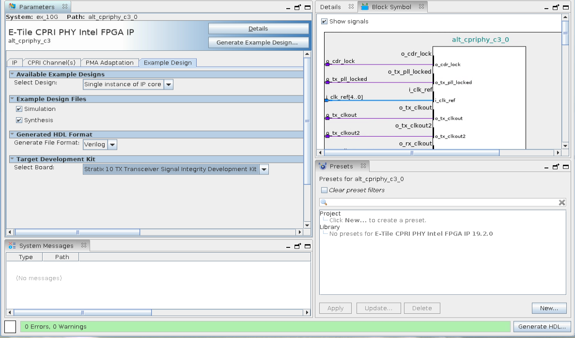
Example Design Tab in the E-tile CPRI PHY Intel® FPGA IP Parameter Editor
If you do not already have an Intel® Quartus® Prime Pro Edition project in which to integrate your E-Tile Hard IP for Ethernet Intel FPGA IP IP core, you must create one.
- In the Intel® Quartus® Prime Pro Edition, click File > New Project Wizard to create a new Quartus Prime project, or File > Open Project to open an existing Intel® Quartus® Prime project. The wizard prompts you to specify a device.
- Specify the device family Intel Stratix 10 and select a device that meets all of these requirements:
- Transceiver tile is E-tile
- Transceiver speed grade is -1 or -2
- Core speed grade is -1 or -2
- Click Finish.
Follow these steps to generate the E-tile CPRI PHY IP hardware design example and testbench:
- In the IP Catalog, locate and select E-tile CPRI PHY Intel® FPGA IP . The New IP Variation window appears.
- Specify a top-level name <your_ip> for your custom IP variation. The parameter editor saves the IP variation settings in a file named <your_ip> .ip.
- Click OK. The parameter editor appears.
- On the IP tab, specify the parameters for your IP core variation.
- The hardware design example provided with enable internal serial loopback by default.
- On the Example Design tab, under Example Design Files, select the Simulation option to generate the testbench and the compilation-only project. Select the Synthesis option to generate the hardware design example. You must select at least one of the Simulation and Synthesis options to generate the design example.
- On the Example Design tab, under Generated HDL Format, select Verilog HDL or VHDL. If you select VHDL, you must simulate the testbench with a mixed-language simulator. The device under test in the ex_<datarate> directory is a VHDL model, but the main testbench file is a System Verilog file.
- Under Target Development Kit, select the Stratix 10 TX Transceiver Signal Integrity Development Kit or select None. The compilation-only and hardware design examples target your project device. For the hardware design to function correctly, you must ensure that your project device is the same device on your development kit.
- Click the Generate Example Design button. The Select Example Design Directory window appears.
- If you want to modify the design example directory path or name from the defaults displayed (alt_cpriphy_c3_0_example_design), browse to the new path and type the new design example directory name (<design_example_dir>).
Related Information