Visible to Intel only — GUID: xlq1564074774084
Ixiasoft
1. E-Tile Transceiver PHY Overview
2. Implementing the Transceiver PHY Layer
3. E-Tile Transceiver PHY Architecture
4. Clock Network
5. PMA Calibration
6. Resetting Transceiver Channels
7. Dynamic Reconfiguration
8. Dynamic Reconfiguration Examples
9. Register Map
10. Debugging E-Tile Transceiver Links
A. E-Tile Channel Placement Tool
B. PMA Direct PAM4 30 Gbps to 57.8 Gbps Implementation
C. Signal Detect Algorithm
D. Detailed Steps for Reconfiguring from Mission Mode to Channel Protection Mode
E. Detailed Steps for Reconfiguring from Channel Protection Mode to Mission Mode
F. Hold Timing Violation
2.2.1. General and Datapath Parameters
2.2.2. PMA Parameters
2.2.3. Core Interface Options
2.2.4. PMA Interface
2.2.5. PMA Adaptation Parameters
2.2.6. Reed Solomon Forward Error Correction (RS-FEC) Parameters
2.2.7. Reset Parameters
2.2.8. Dynamic Reconfiguration Parameters
2.2.9. Deskew Logic
TX Deskew Logic
RX Deskew Logic
RX Deskew Feature Requirements
Enabling RX Deskew Logic
2.2.10. Port Information
2.2.11. PLL Mode
2.2.12. Simplex Support
3.1.1. Transmitter PMA
3.1.2. Receiver PMA
3.1.3. PMA Tuning
3.1.4. Duplex Adaptation Flow
3.1.5. RX Simplex Adaptation Flow
3.1.6. Dynamic Reconfiguration Adaptation Flow
3.1.7. Loopback modes
3.1.8. PMA Interface
3.1.9. TX PMA Bonding
3.1.10. Unused Transceiver Channels
3.1.11. Low Power Mode (LPM)
3.1.10.1. Unused Transceiver Channels in a Used Tile
3.1.10.2. Unused Transceiver Channels in Completely Unused Tiles
3.1.10.3. Unused Transceiver Channels in High-Speed PAM4 Mode
3.1.10.4. Reconfiguring from Mission Mode to Channel Protection Mode
3.1.10.5. Reconfiguring from Channel Protection Mode to Mission Mode
4.2.1. Single 25 Gbps PMA Direct Channel (with FEC) Within a Single FEC Block
4.2.2. Single 10 Gbps PMA Direct Channel (without FEC)
4.2.3. Four 25 Gbps PMA Direct Channel (with FEC) within a Single FEC Block
4.2.4. PMA Direct 25 Gbps x 4 (FEC Off)
4.2.5. PMA Direct 10.3125 Gbps x 4
4.2.6. PMA Direct 100GE Gbps (25 Gbps x 4) (FEC On)
4.2.7. PMA Direct 100GE PAM4 (50 Gbps x 2) (Aggregate FEC On)
4.2.8. PMA Direct High Data Rate (FEC Off)
6.1. When Is Reset Required?
6.2. How Do I Reset?
6.3. Reset Block Architecture
6.4. PMA Analog Reset
6.5. High Level Specification
6.6. Master-Slave Clocking Option 2 Reset Details
6.7. Quartus® Prime Instantiated Transceiver Reset Sequencer
6.8. Block Diagrams
6.9. Interfaces
6.10. Resetting Transceiver Channels Revision History
7.1. Dynamically Reconfiguring Channel Blocks
7.2. Dynamic Reconfiguration Maximum Data Rate Switch
7.3. Interacting with the Dynamic Reconfiguration Interface
7.4. Unsupported Features
7.5. Reading from the Dynamic Reconfiguration Interface
7.6. Writing to the Dynamic Reconfiguration Interface
7.7. Multiple Reconfiguration Profiles
7.8. Arbitration
7.9. Recommendations for PMA Dynamic Reconfiguration
7.10. Steps to Perform Dynamic Reconfiguration
7.11. PMA Attribute Details
7.12. Dynamic Reconfiguration Flow for Special Cases
7.13. Ports and Parameters
7.14. Embedded Debug Features
7.15. Timing Closure Recommendations
7.16. Transceiver Register Map
7.17. Loading IP Configuration Settings
7.18. Dynamic Reconfiguration Revision History
8.1. Reconfiguring the Duplex PMA Using the Reset Controller in Automatic Mode
8.2. PRBS Usage Model
8.3. PMA Error Injection
8.4. PMA Receiver Equalization Adaptation Usage Model
8.5. User-Defined Pattern Example
8.6. Configuring the Attenuation Value (VOD)
8.7. Configuring the Post Emphasis Value
8.8. Configuring pretap1 Values
8.9. Inverting TX Polarity for the PMA Driver
8.10. Inverting RX Polarity for the PMA Driver
8.11. Configuring a PMA Parameter Tunable by the Adaptive Engine
8.12. Configuring a PMA Parameter Using Native PHY IP
8.13. Enabling Low Power Mode for Multiple Channels
8.14. Initializing an RX
8.15. Resetting the RX Equalization
8.16. Dynamic Reconfiguration Examples Revision History
9.2.1. 0x0001: PMA Enable/Disable
9.2.2. 0x0002: PMA PRBS Settings
9.2.3. 0x0003: Data Comparison Set Up and Start/Stop
9.2.4. 0x0005: TX Channel Divide By Ratio
9.2.5. 0x0006: RX Channel Divide By Ratio
9.2.6. 0x0008: Internal Serial Loopback and Reverse Parallel Loopback Control
9.2.7. 0x000A: Receiver Tuning Controls
9.2.8. 0x000E: RX Phase Slip
9.2.9. 0x0011: PMA TX/RX Calibration
9.2.10. 0x0013: TX/RX Polarity and Gray Code Encoding
9.2.11. 0x0014: TX/RX Width Mode
9.2.12. 0x0015: TX Equalization
9.2.13. 0x0017: Error Counter Reset
9.2.14. 0x0018: Status/Debug Register
9.2.15. 0x0019: Status/Debug Register Next Write Field
9.2.16. 0x001A: Status/Debug Register Next Read Field
9.2.17. 0x001B: TX Error Injection Signal
9.2.18. 0x001C: Incoming RX Data Capture
9.2.19. 0x001E: Error Count Status
9.2.20. 0x0020: Electrical Idle Detector
9.2.21. 0x002B: RX Termination and TX Driver Tri-state Behavior
9.2.22. 0x0030: PMA Mux Clock Swap
9.2.23. 0x0126: Read Receiver Tuning Parameters
9.2.24. Reading and Writing PMA Analog Parameters Using Attributes
9.2.24.1. Reading PMA Analog Parameters
9.2.24.2. Updating PMA Analog Parameters
9.2.24.3. Loading Parameters into the Receiver
9.2.24.4. Fixing Parameter Values
9.2.24.5. Reading NRZ/PAM4 Eye Height
9.2.24.6. Enabling and Disabling Electrical Idle Detector Filtering and Reading Electrical Idle Detector Status
9.2.24.7. Initial Adaptation Effort Levels
9.5.1. rsfec_top_clk_cfg
9.5.2. rsfec_top_tx_cfg
9.5.3. rsfec_top_rx_cfg
9.5.4. tx_aib_dsk_conf
9.5.5. rsfec_core_cfg
9.5.6. rsfec_lane_cfg
9.5.7. tx_aib_dsk_status
9.5.8. rsfec_debug_cfg
9.5.9. rsfec_lane_tx_stat
9.5.10. rsfec_lane_tx_hold
9.5.11. rsfec_lane_tx_inten
9.5.12. rsfec_lane_rx_stat
9.5.13. rsfec_lane_rx_hold
9.5.14. rsfec_lane_rx_inten
9.5.15. rsfec_lanes_rx_stat
9.5.16. rsfec_lanes_rx_hold
9.5.17. rsfec_lanes_rx_inten
9.5.18. rsfec_ln_mapping_rx
9.5.19. rsfec_ln_skew_rx
9.5.20. rsfec_cw_pos_rx
9.5.21. rsfec_core_ecc_hold
9.5.22. rsfec_err_inj_tx
9.5.23. rsfec_err_val_tx
9.5.24. rsfec_corr_cw_cnt (Low)
9.5.25. rsfec_corr_cw_cnt (High)
9.5.26. rsfec_uncorr_cw_cnt (Low)
9.5.27. rsfec_uncorr_cw_cnt (High)
9.5.28. rsfec_corr_syms_cnt (Low)
9.5.29. rsfec_corr_syms_cnt (High)
9.5.30. rsfec_corr_0s_cnt (Low)
9.5.31. rsfec_corr_0s_cnt (High)
9.5.32. rsfec_corr_1s_cnt (Low)
9.5.33. rsfec_corr_1s_cnt (High)
10.1. E-Tile Transceiver Toolkit Overview
10.2. E-Tile Transceiver Debugging Flow Walkthrough
10.3. Modifying the Design to Enable E-Tile Transceiver Debug
10.4. Programming the Design into an Intel FPGA
10.5. Loading the Design in the E-Tile Transceiver Toolkit
10.6. Verifying E-Tile Hardware Connections
10.7. Running Transceiver Tests
10.8. Controlling PMA Analog Settings
10.9. Debugging E-Tile Transceiver Links Revision History
B.1. Building Blocks and Considerations
B.2. Starting a New Quartus® Prime Pro Edition Design
B.3. Selecting the Configuration Clock Source
B.4. Instantiating the Transceiver Native PHY IP
B.5. Instantiating the In-system Sources and Probes Intel® FPGA IP
B.6. Making the Top Level Connection
B.7. Assigning Pins
B.8. Bringing up the Board
B.9. Debug Tools
B.10. PMA Direct PAM4 30 Gbps to 57.8 Gbps Implementation Revision History
Visible to Intel only — GUID: xlq1564074774084
Ixiasoft
2.2.9. Deskew Logic
TX Deskew Logic
Once bonding is enabled (or, in PMA direct high data rate mode, even if bonding is not enabled) deskew logic in the transceiver interface is engaged, which aligns the data that is transferred across multiple channels within the same clock cycle. However, deskew logic requires action on your part. Bit 33 of the TX parallel data, data[33], is mapped to function as the deskew pulse. For PMA Direct high data rate, you must drive the deskew pulse bit of all bonded channels with a pulse that is active on every eighth parallel clock cycle. The deskew logic uses the deskew pulse to align the FIFO. It takes several cycles for the channels to be aligned. You must perform an Avalon® memory-mapped interface read to the TX deskew status register cfg_tx_deskew_sts of all bonded lanes to find out if deskew completed successfully which indicates that all bonded channels have aligned parallel data. The deskew status register also provides further information for debugging if deskew is not successful.
cfg_tx_deskew_sts[2]
- 0 = not aligned or not enabled or did not receive a deskew bit
- 1 = aligned
cfg_tx_deskew_sts[1:0]
- 00 = not yet received a deskew bit
- 01 = not aligned
- 10 = received one set of aligned deskew bits
- 11 = received 16 sets of aligned deskew bits
The deskew mechanism runs continuously. In other words, if the alignment lock is lost, monitoring cfg_tx_deskew_sts informs you about the status. The deskew mechanism works the same way for PMA direct high data rate PAM4 mode for two EMIB channels. In other words, you must send deskew pulses for the data you sent to two EMIBs and at the master PMA interface you are aligned to before sending to a single PMA. In double width mode, the deskew pulse needs to be sent every fourth half clock cycle.
Figure 36. Deskew Pulse with Double Width Mode Off (Full-Rate)
Figure 37. Deskew Pulse with Double Width Mode On (Half-Rate)
For the extra data bit's detailed usage, contact My Intel support.
| E-Tile Native PHY IP Mode | TX/RX PMA Interface Width | Enable TX/RX Double Width Transfer | Valid Parallel Data | Deskew Bits | Pulse Clock Cycle |
|---|---|---|---|---|---|
| PMA Direct | 16 | No | Data [15:0] | Data[33] | 8th cycle |
| PMA Direct | 20 | No | Data[19:0] | Data[33] | 8th cycle |
| PMA Direct | 32 | No | Data[31:0] | Data[33] | 8th cycle |
| PMA Direct | 40 | No | Data[39:0] | Not supported | Not supported |
| PMA Direct | 16 | Yes | Data[55:40] Data[15:0] |
Data[33] | 4th cycle |
| PMA Direct | 20 | Yes | Data[59:40] Data[19:0] |
Data[33] | 4th cycle |
| PMA Direct | 32 | Yes | Data[71:40] Data [31:0] |
Data[33] | 4th cycle |
| PMA direct high data rate PAM4 | 64 | No | Data[111:80] Data[31:0] |
Data[33] Data[113] |
8th cycle |
| PMA direct high data rate PAM4 | 64 | Yes | Data[151:120] Data[71:40] Data[111:80] Data[31:0] |
Data[33] Data[113] |
4th cycle |
RX Deskew Logic
For PAM4 dual channel mode, the data comes from two EMIBs, so there can be skews in between. To mitigate this, the Native PHY IP implements a deskew function on RX side to align the two EMIBs' data. However, you can only enable this deskew function when the Native PHY IP is configured in PMA direct high data rate PAM4 mode. The deskew logic samples the deskew bit of rx_parallel_data to detect if there is any misalignment. If there is misalignment, the deskew logic calculates skew cycles and outputs the aligned data.
The deskew logic can mitigate a maximum of two skew cycles for single width transfer and a maximum of one skew cycle for double width transfer. When the deskew logic is enabled, there is an added latency of up to three clock cycles even if there is no skew and an added latency of up to five clock cycles if there is two skew cycles.
To observe the misalignment, read the deskew bit in rx_parallel_data[159:0], which is divided into lane 0 (ln0 or rx_parallel_data [79:0]) and lane 1 (ln1 or rx_parallel_data[159:80]).
If it is single data width transfer, the deskew bit is bit [33].
Figure 38. Single Data Width Transfer
If it is double data width transfer, both deskew bits [33] and [73] are valid. However, one appears in each channel, so there are four possible combinations:
- ln0[33] and ln1[33]
- ln0[33] and ln1[73]
- ln0[73] and ln1[33]
- ln0[73] and ln1[73]
Figure 39. Double Data Width Transfer
RX Deskew Feature Requirements
- The Native PHY IP must be configured in PMA direct high data rate PAM4 mode.
- The two EMIB channel clocks must be tied together to run on one clock domain.
Figure 40. Two EMIB Channel Clocks Working in the Same Clock Domain
- rx_ready must show that the receiver is ready. If the receiver is not ready, the data is neither reliable nor ready. So you must reset the reset controller until rx_ready indicates that the receiver is ready.
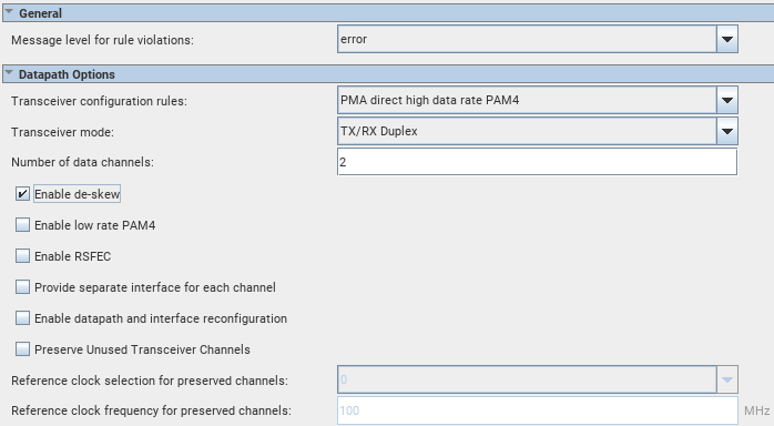
Enabling RX Deskew Logic
- From Native PHY IP GUI, select from Transceiver configuration rules > PMA direct high data rate PAM4.
- Turn on Enable de-skew.
- Because RX deskew logic is applicable for PMA direct high data rate PAM4 only, turn off Enable RSFEC.
- Verify that your data is aligned by confirming that rx_dskw_ready is asserted.
Figure 41. Enabling RX Deskew Logic
Related Information