Visible to Intel only — GUID: kux1613963837075
Ixiasoft
1. Acronyms
2. Introduction
3. IP Architecture and Functional Description
4. Advanced Features
5. Interfaces
6. Parameters
7. Testbench
8. Troubleshooting/Debugging
9. F-Tile Avalon Streaming Intel FPGA IP for PCI Express User Guide Archives
10. Revision History for the F-Tile Avalon Streaming Intel FPGA IP for PCI Express User Guide
A. Configuration Space Registers
B. Implementation of Address Translation Services (ATS) in Endpoint Mode
C. Packets Forwarded to the User Application in TLP Bypass Mode
D. Root Port Enumeration
E. Bifurcated Endpoint Support for Independent Resets
3.1. Architecture
3.2. Functional Description
3.3. Avalon-ST TX/RX
3.4. Interrupts
3.5. Completion Timeout
3.6. Hot Plug
3.7. Power Management
3.8. Configuration Output Interface (COI)
3.9. Configuration Intercept Interface (EP Only)
3.10. Hard IP Reconfiguration Interface
3.11. PHY Reconfiguration Interface
3.12. Page Request Service (PRS) (EP Only)
5.1. Overview
5.2. Clocks and Resets
5.3. Serial Data Interface
5.4. Avalon-ST Interface
5.5. Interrupt Interface
5.6. Hard IP Status Interface
5.7. Error Interface
5.8. 10-bit Tag Support Interface
5.9. Completion Timeout Interface
5.10. Power Management Interface
5.11. Hot Plug Interface (RP Only)
5.12. Configuration Output Interface
5.13. Configuration Intercept Interface (EP Only)
5.14. Hard IP Reconfiguration Interface
5.15. PHY Reconfiguration Interface
5.16. Page Request Service (PRS) Interface (EP Only)
5.17. FLR Interface Signals
5.18. PTM Interface Signals
5.19. VF Error Flag Interface Signals
5.20. VirtIO PCI Configuration Access Interface Signals
6.2.3.1. Device Capabilities
6.2.3.2. Link Capabilities
6.2.3.3. Legacy Interrupt Pin Register
6.2.3.4. MSI Capabilities
6.2.3.5. MSI-X Capabilities
6.2.3.6. Slot Capabilities
6.2.3.7. Latency Tolerance Reporting (LTR)
6.2.3.8. Process Address Space ID (PASID)
6.2.3.9. Device Serial Number Capability
6.2.3.10. Page Request Service (PRS)
6.2.3.11. Access Control Service (ACS) Capabilities
6.2.3.12. Power Management
6.2.3.13. Vendor Specific Extended Capability (VSEC) Registers
6.2.3.14. Precision Time Measurement (PTM)
6.2.3.15. Address Translation Services (ATS)
6.2.3.16. TLP Processing Hints (TPH)
6.2.3.17. VirtIO Parameters
6.2.3.18. Receiver Detection
7.6.1. ebfm_barwr Procedure
7.6.2. ebfm_barwr_imm Procedure
7.6.3. ebfm_barrd_wait Procedure
7.6.4. ebfm_barrd_nowt Procedure
7.6.5. ebfm_cfgwr_imm_wait Procedure
7.6.6. ebfm_cfgwr_imm_nowt Procedure
7.6.7. ebfm_cfgrd_wait Procedure
7.6.8. ebfm_cfgrd_nowt Procedure
7.6.9. BFM Configuration Procedures
7.6.10. BFM Shared Memory Access Procedures
7.6.11. BFM Log and Message Procedures
7.6.12. Verilog HDL Formatting Functions
A.3.1. Intel-Defined VSEC Capability Header (Offset 00h)
A.3.2. Intel-Defined Vendor Specific Header (Offset 04h)
A.3.3. Intel Marker (Offset 08h)
A.3.4. JTAG Silicon ID (Offset 0x0C - 0x18)
A.3.5. User Configurable Device and Board ID (Offset 0x1C - 0x1D)
A.3.6. General Purpose Control and Status Register (Offset 0x30)
A.3.7. Uncorrectable Internal Error Status Register (Offset 0x34)
A.3.8. Uncorrectable Internal Error Mask Register (Offset 0x38)
A.3.9. Correctable Internal Error Status Register (Offset 0x3C)
A.3.10. Correctable Internal Error Mask Register (Offset 0x40)
Visible to Intel only — GUID: kux1613963837075
Ixiasoft
3.1.2. Refclk
There are ten reference clock pins for FGT PMAs at the package level. Eight of the FGT reference clocks (refclk[0]-refclk[7]) can be used as reference clock inputs for PCI Express channels. There are up to four reference clock ports (refclk0 – refclk3) in the F-Tile Avalon Streaming IP for PCI Express depending on the Hard IP mode configuration in the IP. For Hard IP modes that span more than one FGT quads, you must use reference clock pins that are accessible by the quads. Depending on the HIP mode, you must assign the reference clock ports of the IP to corresponding reference clock pins in your Intel® Quartus® Prime design.
The F-Tile Reference and System PLL Clocks Intel FPGA IP is a required IP for F-tile Avalon Streaming PCI Express designs. It configures the reference clock for the PCI Express channels and also configures the System PLL.
Note: Refer to the Implementing the F-Tile Reference and System PLL Clocks Intel FPGA IP section in the F-Tile Architecture and PMA and FEC Direct PHY IP User Guide for information about this IP.
The table below shows the mapping of reference clock pins to the reference clock ports of the F-Tile Avalon Streaming IP for PCI Express depending on the Hard IP mode.
| Mode | refclk0 port | refclk1 port | refclk2 port | refclk3 port |
|---|---|---|---|---|
| 1 x16 | refclk[2] or refclk[3] or refclk[4] or refclk[5] pin | refclk[2] or refclk[3] or refclk[4] or refclk[5] pin | N/A | N/A |
| 1 x8 | refclk[0] or refclk[1] or refclk[2] or refclk[3] or refclk[4] or reflck[5] pin | refclk[0] or refclk[1] or refclk[2] or refclk[3] or refclk[4] or reflck[5] pin | N/A | N/A |
| 2 x8 | refclk[0] or refclk[1] or refclk[2] or refclk[3] or refclk[4] or reflck[5] pin | refclk[2] or refclk[3] or refclk[4] or refclk[5] or refclk[6] or reflck[7] pin | N/A | N/A |
| 1 x4 | refclk[0] or refclk[1] or refclk[2] or refclk[3] or refclk[4] or reflck[5] pin | refclk[0] or refclk[1] or refclk[2] or refclk[3] or refclk[4] or reflck[5] pin | N/A | N/A |
| 2 x4 | refclk[0] or refclk[1] or refclk[2] or refclk[3] or refclk[4] or reflck[5] pin | refclk[0] or refclk[1] or refclk[2] or refclk[3] or refclk[4] or reflck[5] pin | N/A | N/A |
| 4 x4 | refclk[0] or refclk[1] or refclk[2] or refclk[3] or refclk[4] or reflck[5] pin | refclk[2] or refclk[3] or refclk[4] or refclk[5] or refclk[6] or reflck[7] pin | refclk[0] or refclk[1] or refclk[2] or refclk[3] or refclk[4] or reflck[5] pin | refclk[2] or refclk[3] or refclk[4] or refclk[5] or refclk[6] or reflck[7] pin |
Note:
- For 1 x16, 1 x8 and 1 x4 modes, both refclk0 and refclk1 ports need to be connected to a single outrefclk_fgt_i (i = 0 to 7) port from “F-Tile Reference and SystemPLL Clocks” IP.
- For 2 x8, 2 x4 and 4 x4 modes, user has an option to share a single refclk source across all the refclk port, connect to a single outrefclk_fgt_i (i = 0 to 7) port from “F-Tile Reference and SystemPLL Clocks” IP.
- Independent refclk source is supported for 2 x4, 2 x8 and 4 x4 modes.
Note: For additional information about reference clock pins and reference clock network, refer to the Reference Clock Network section in F-Tile Architecture and PMA and FEC Direct PHY IP User Guide.
Figure 4. Single 100 MHz Clock Source in 2x8 Mode
Figure 5. Independent 100 MHz Clock Source in 2x8 Mode
In 2x8 mode, you can drive the refclk0 and refclk1 ports with either a single 100 MHz clock source connected to a reference clock pin at package level, or two independent 100 MHz sources depending on your system architecture. For example, if your system has each x8 port connected to a separate CPU/Root Complex, it may be necessary to drive the reference clock pins using independent clock sources. PERST# needs to indicate the stability of the clock source.
Figure 6. Single 100 MHz Clock Sources in 4x4 Mode
Figure 7. Independent 100 MHz Clock Sources in 4x4 Mode
In 4x4 mode, you can drive the refclk0 to refclk3 ports with either a single 100 MHz clock source connect to a reference clock pin at package level, or two independent 100 MHz clock sources or four independent clock sources depending on your system architecture. PERST# needs to indicate the stability of the clock source.
One of the reference clock pins refclk[0] to refclk[7] can also be shared as the reference clock to the System PLL which generates the pld_clk and coreclkout_hip clocks. The reference clock must adhere to the following requirements:
- If compliance to PCIe link training timing specifications is required, the reference clock to the System PLL must be available and stable before device configuration begins. You must set the Refclk is available at power-on parameter in the System PLL IP to On. Derive the reference clock from an independent and free-running clock source. Alternatively, if the reference clock from the PCIe link is guaranteed available before device configuration starts, you can use it to drive the System PLL. Once the PCIe link refclk is alive, it can never be allowed to go down.
- If compliance to PCIe link training timing specifications is not required and the reference clock to the System PLL may not be available before device configuration starts, you must set the Refclk is available at power-on parameter in the System PLL IP to Off. In this case, you may use the reference clock from the PCIe link to drive the System PLL. The System PLL does not lock to the reference clock until you perform the global Avalon memory-mapped interface write operations signaling that the reference clock is available.
Note: Refer to the Example Flow to Indicate All System PLL Reference Clocks are Ready section in the F-Tile Architecture and PMA and FEC Direct PHY IP User Guide for details on how to trigger the System PLL to lock to the reference clock.
The figure below shows an example where an independent reference clock drives the System PLL (via the in_refclk_fgt_0 port). It does not share the reference clock from the PCIe link which is not available before device configuration starts.
Figure 8. Independent Refclk to System PLL
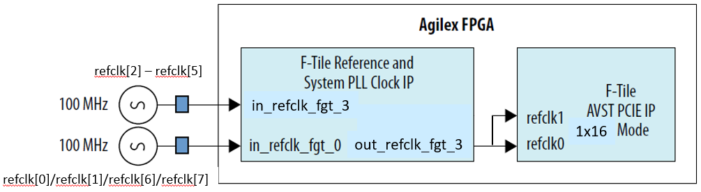
Once the reference clock for the System PLL is up, it must be stable and present throughout the device operation and must not go down. If you are not able to adhere to this requirement, you must reconfigure the device.
Note: For additional information of restrictions on reference clock and the System PLL, refer to the Clock Rules and Restrictions section in F-Tile Architecture and PMA and FEC Direct PHY IP User Guide.
Related Information