Visible to Intel only — GUID: cru1442968622720
Ixiasoft
1. Nios II Custom Instruction Overview
2. Custom Instruction Hardware Interface
3. Custom Instruction Software Interface
4. Design Example: Cyclic Redundancy Check
5. Introduction to Nios® II Floating Point Custom Instructions
6. Nios II Floating Point Hardware 2 Component
7. Nios® II Floating Point Hardware (FPH1) Component
8. Document Revision History for Nios II Custom Instruction User Guide
4.1.1. Setting up the Environment for the CRC Example Design
4.1.2. Opening the Component Editor
4.1.3. Specifying the Custom Instruction Component Type
4.1.4. Displaying the Custom Instruction Block Symbol
4.1.5. Adding the CRC Custom Instruction HDL Files
4.1.6. Configuring the Custom Instruction Parameter Type
4.1.7. Setting Up the CRC Custom Instruction Interfaces
4.1.8. Configuring the Custom Instruction Signal Type
4.1.9. Saving and Adding the CRC Custom Instruction
4.1.10. Generating and Compiling the CRC Example System
6.1. Overview of the Floating Point Hardware 2 Component
6.2. Floating Point Hardware 2 IEEE 754 Compliance
6.3. IEEE 754 Exception Conditions with FPH2
6.4. Floating Point Hardware 2 Operations
6.5. Building the FPH2 Example Hardware
6.6. Building the FPH2 Example Software
6.7. FPH2 Implementation of GCC Options
6.8. Nios II FPH2 and the Newlib Library
6.9. C Macros for round(), fmins(), and fmaxs()
Visible to Intel only — GUID: cru1442968622720
Ixiasoft
4.1.8. Configuring the Custom Instruction Signal Type
To configure the custom instruction signal type, follow these steps:
- In the View menu, click Signals to open the Signals tab.
Figure 18. Custom Instruction Signal Types
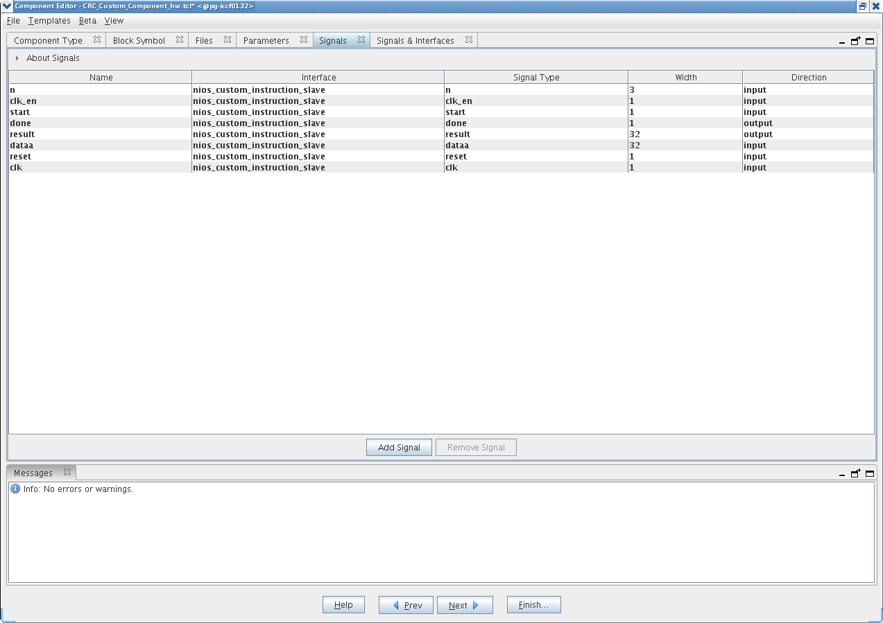
- For each signal in the list, follow these steps:
- Select the signal name.
- In the Interface column, select the name of the interface to which you want to assign the signal.
In the design example, select nios_custom_instruction_slave for all signals. These selections ensure that the signals appear together on a single interface, and that the interface corresponds to the design example files in the crc_hw folder.
- In the Signal Type column, select one of the standard hardware ports listed in “Custom Instruction Types”. In the design example, each signal must be mapped to the signal type of the same name.
- Open the Signals and Interfaces tab.
Figure 19. Signals and Interfaces
 The parameters for Clock Cycle Type automatically change to "Variable" because the design example builds a variable multicycle type custom instruction. For other designs, you enter the correct clock cycle type for your custom instruction design:
- "Variable" for a variable multicycle type custom instruction
- "Multicycle" for a fixed multicycle type custom instruction
- "Combinatorial" for a combinational type custom instruction.
If the interface does not include a clk signal, the component editor automatically infers that the interface is a combinational type interface. If the interface includes a clk signal, the component editor automatically infers that the interface is a multicycle interface. If the interface does not include a done signal, the component editor infers that the interface is a fixed multicycle type interface. If the interface includes a done signal, the component editor infers that the interface is a variable multicycle type interface.
Related Information