Instantiate a Memory Tester Subsystem as a Generic Component
At this stage of memory tester subsystem design, you can use Platform Designer to assemble the whole design to verify and debug components such as the Nios® II logic resource usage and DDR4 Calibration.
You can instantiate the memory tester subsystem as a generic component (an empty entity with only interfaces defined). When integrating a memory tester subsystem with a processor subsystem and an EMIF controller only the interfaces of the memory tester subsystem are significant.
Instantiation of a generic component does not prevent the completion of other parts of the design. This feature provides a lot of flexibility in the design, and is especially beneficial for large and team-based designs. You need only verify that, when adding the entity implementation, the entity interfaces match the interfaces defined for the generic component.
To instantiate a generic component:
- In the IP Catalog, double-click Generic Component.
Figure 21. IP Catalog Generic Component
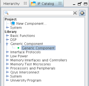
The Component Instantiation tab contains three implementation types: IP, HDL, and Blackbox. When you add a generic component, Blackbox is the default.
- Change the HDL entity name and HDL compilation library to memory_tester_subsystem.
Figure 22. Component Instantiation Tab for memory_tester_subsystem Generic Component
- To add the component, click Finish.
- Right-click the name of the top_system_generic_component_0 component and click Rename. Type memory_tester_subsystem.
Note: When implementing a generic component with the Blackbox option, you don’t have to provide the HDL implementation during component instantiation. Simply customize the interfaces and signals and generate an empty HDL file. Then, connect the generic component to other components in Platform Designer, generate interconnects, and finally, compile the project with this empty entity. When you finish the implementation of the generic component, simply replace the generic component with the actual implementation to complete the design. In other words, the generic component functions as a placeholder for the actual component you plan to use.
Platform Designer provides many features to help you add interfaces and signals for a generic component. The following steps, 1-11, showcase how to add signals manually, by using Mirror or Clone, and how to change parameters. In the final steps, you are going to import a complete interface definition from an .ipxact file.
Platform Designer provides many ways to help you add interfaces easily and efficiently.
- Click .
- Select the memory_tester_subsystem component. The instantiation information appears in the Component Instantiation tab.
- Click the Signals & Interfaces tab. You can add interfaces manually, Import from an IP-XACT file, Mirror, or Clone from existing interfaces in the system.
- Click << add interface>> and select Clock Input from the drop down list.
- To change the name of the interface, in the Name field, type clk.
- Click <<add signal>> and choose clk.
- Repeat steps 4-6 to add a Reset Input interface and signal, and rename it reset.
- Click Apply.
Figure 23. Signal and Interface Options for memory_tester_subsystem
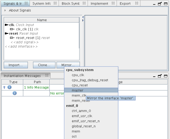
Apart from clock and reset, the design also requires an Avalon-MM slave interface to communicate with the processor subsystem. It could be tedious to add Avalon-MM slave interface manually since there are address bus, data bus, and many other parameter settings to configure. An easier way is to use the Mirror feature.
- Click Mirror and choose the master interface of cpu_subsystem to add a slave interface.
Figure 24. Create Mirror of Interface 'master'
- You can resolve the errors that appear in the Instantiation Messages box by assigning Associated Clock and Associated Reset to the clk and reset interfaces in the parameter editor.
- Locate the Maximum pending read transactions box under Pipelined Transfers and change that value to 4.
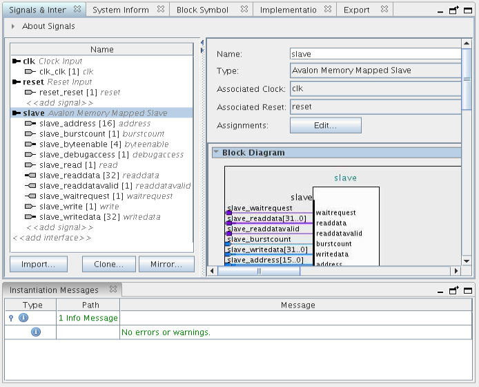
- Click Import and choose memory_tester_subsystem_bb.ipxact to add the interfaces.
- To complete the import step, click Apply.
Figure 25. Results of Importing memory_tester_subsystem_ bb.ipxact

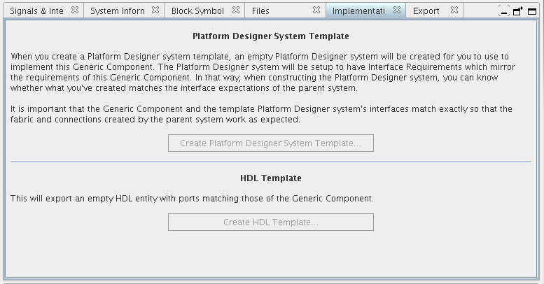
Click the Implementation tab to create a Platform Designer template with interface requirements setup to implement the memory tester subsystem. You can also create an HDL template with ports defined.
- Click to create the memory_tester_ subsystem.qsys file in the <project folder>.
- Click to create the memory_tester_ subsystem.v file in the <project folder>.
The Export tab allows you to export the interfaces and requirements to an .ipxact or a _hw.tcl file, however, this feature is not used in this project.
Figure 26. Create Platform Designer System Template and HDL Template Options