Visible to Intel only — GUID: vdw1496958852418
Ixiasoft
Add Clock, Reset, and Avalon-MM components
Add Pre-Built Systems and Memory Test Microcore Components
Export Signals, Set Base Address Assignments, and Connect Memory Tester Interface Components
Resolve Interface Requirements and Value Mismatches
Replace the memory_tester_subsystem Generic Component
Synchronize IP Results
Visible to Intel only — GUID: vdw1496958852418
Ixiasoft
Resolve Interface Requirements and Value Mismatches
In the Interface Requirements tab you can verify that the exported interfaces meet the interface requirements.
- Click the Interface Requirements tab in Platform Designer.
The exported interfaces in the tutorial system appear in the Current System list. The Interface Requirements list shows the definition of the generic component. A green highlight indicates a missing item. A blue highlight indicates an item with parameter mismatches.
Figure 33. Missing Components and Value Mismatches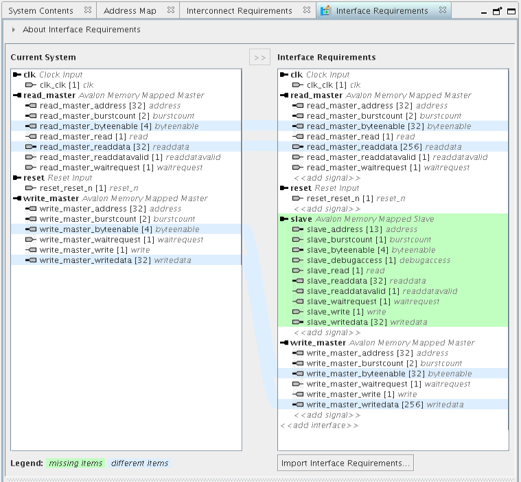
- View the Interface Requirements list for missing items. What appears in the figure indicates a missing slave interface of the pipeline bridge. Fix the missing items by exporting the appropriate signal.
- In the System Contents tab, double-click the entry in the Export column corresponding to the s0 for the mm_bridge component and rename it to slave.
Figure 34. Export and Rename Avalon-MM Slave
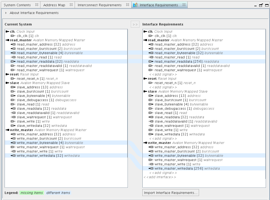
- Re-examine the Interface Requirements tab. The Current System list contains the slave interface with no green highlight. Next you resolve the different item highlighted in blue.
Figure 35. Current System / Interface Requirement Value Mismatch
- Click the signal name highlighted in blue to display more information in the Parameter Differences pane. Typically, you change the Current System Value to match the Interface Requirement Value by editing the parameters of that component.
Figure 36. Changing Current System Value
- Click read_master_readdata[32] and examine the Parameter Differences pane. In the top_system, the data width of the Avalon Memory Mapped Master of the EMIF controller is 256. The data width of the memory_tester_subsystem must match with a value of 256. Adapters inserted to handle data width mismatch may become the bottle-neck of a design.
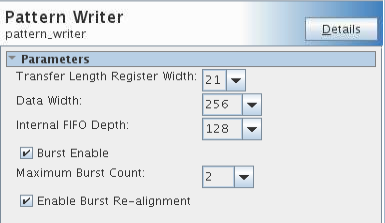
- This exported interface comes from the Pattern Writer. To alter its width, alter the parameters of that IP core. To change the data width of Pattern Writer, double-click the pattern_writer component. Change the Data Width in the parameter editor to 256.
Figure 37. Pattern Writer Settings Dialog Box
Repeat the Step 7 for the pattern_reader component.
Figure 38. Pattern Reader Settings Dialog Box
These parameter changes alter the width of *_byteenable signals accordingly.
- Verify that your Interface Requirements tab contains no missing items or mismatched items. In cases where you want to keep the current system value, you can click the Copy button to copy items from the left table to the right.
Figure 39. Completed Interface Requirements

This completes the editing of component parameters to validate interface requirements.
- Save and close the project. There is no requirement to generate HDL because we are replacing the generic component in top_system.qsys with the implemented subsystem.
-
Close Platform Designer and inspect the Files tab in the Project Navigator. Files for the memory_tester_subsystem are present in the Intel® Quartus® Prime Pro Edition project.
Figure 40. Files List for memory_tester_subsystem.v